
The MFEA Encoder
For our robotic arm to work effectively, a rotary encoder had to be found. A baseline specification for such an encoder was established by compiling a system error budget of which the rotary encoder forms part. From this, it was determined that an angular encoder was required with the following baseline specification:
16 bit resolution.
0.112 mrad (0.006°) accuracy.
0.056 mrad (0.003°) repeatability.
Ability to work in harsh environments without performance degradation.
The problem was we could not find an encoder satisfying our baseline specification. As a result, we decided to build our own. And after many months of development, we were able to produce an encoder able to surpass the performances of current best-in-class encoders available on the market. During a series of tests at room temperature the static accuracy of our prototype ADM3 was measured and found to be in the order of 0,07 mrad (0.004°) with repeatability of 0.035 mrad (0.002°).
We were thrilled by the exceptional performance of our encoder, prompting us to take the natural step of patenting this groundbreaking technology. Our MFEA technology was safeguarded through a provisional patent in 2021, followed by a PCT application (PCT/IB2022/060508) which was made public by WIPO on May 11, 2023 (Publication Number WO/2023/079435). You can find the PCT publication link below.
https://patentscope.wipo.int/search/en/detail.jsf?docId=WO2023079435&_cid=P11-LI5VOS-50497-1
Our encoder, named MFEA, signifies Magnetic Field Effect Angular, with the exclusion of the "E" from "Encoder" for practical reasons. Our innovation led us to a novel method of accurately and reliably measuring angles, particularly excelling in challenging environments characterized by oil, grease, dust, and moisture - environments frequently encountered in industrial settings and factory automation. Notably, the electronic components and assembly processes of our encoder remain uncomplicated, relying on straightforward PCB electronics applied in a creative way.
-
A ferrite toroid was installed around the Main Spindle of the Forearm Actuator. It was installed off-centre to introduce a wobble when the spindle rotates. The PCB layout of MFEA Encoder ADM1 model as illustrated here was comprised of 2 Colpitts Oscillators placed on a rectangular PCB. Note that two Colpitts Oscillators were used in order to eliminate the duplicate solution problem (two Primary Spindle angles for a given Colpitts Frequency) that arises when a single Colpitts Oscillator is used.
MFEA Encoder ADM1 model was installed adjacent to the Main Spindle, perpendicular to the wobbling toroid’s outer diameter surface. This initial configuration was chosen to ensure easy replacement of the PCB without having to remove the Main Spindle. However, it placed the inductor coils L2 and L4 too far away and at odd angles with the wobbling toroid. This arrangement was unable to produce a small enough air gap, calling for a new arrangement in subsequent models.
-
As the spindle rotates, the “overlap area” formed between the inductor coils (in red) and the wobbling ferrite toroid (in blue) varies. This variation in overlap area results in a variation of inductance resulting in the frequency variations of two separate Colpitts oscillators juxtaposed 90° from each other.
Each oscillator is buffered with a voltage comparator, producing two high-speed digital signals feeding two binary counters in a common microprocessor (not shown here). The counters determine the number of pulses produced by each oscillator during a precise period. The microprocessor uses these count values to determine with high precision the angle of the spindle.
-
ADM2 was comprised of a PCB layout arranged around the spindle as illustrated here. A rotor comprising a ferrite toroid mounted on a moveable bobbin allowed the air gap to be adjusted. It was determined at this stage that the PCB of MFEA Encoder ADM2 model would be in the form of a horse shoe to ensure easy installation/removal without the need to remove the main spindle during installation.
-
This picture was taken during the integration of the MFEA Encoder ADM2 model with the Forearm Actuator ADM3 model. As shown, the encoder was installed with studs affixed with screws from the outside of the actuator chassis. Electrical signals of the encoder were passed via a D-type connector.
This type of installation does not bid well for accuracy and repeatability but is necessary for producing a low-cost robotic arm where high-precision machining must be avoided. What was needed is a mechanism whereby the encoder could automatically find its position and orientation by itself. This was the impetus leading to the auto-align algorithm of subsequent MFEA encoders.
-
This picture shows the result of integrating the MFEA Encoder ADM2 model with the Forearm Actuator ADM3 model. Subsequent testing of this system showed inadequate resolution in measuring the angle of the Main Spindle. Although it worked well, this system was unable to achieve our original goal of 0,5mm end-effector positional accuracy and called for increasing the frequencies of the Colpitts Oscillators. To do this, measures had to be taken to avoid overflow of the binary counters in the microprocessor. These measures led to the MFEA ADM3 configuration.
-
To increase the dynamic range of the binary counters employed in the encoder a 3rd Colpitts Oscillator referred to as the Bias Oscillator was added in the MFEA Encoder ADM3 model. The bias oscillator was installed in between the 2 main oscillators with all 3 oscillators juxtaposed at 90° from each other. By multiplying (using a balanced modulator) the signals produced by Oscillators 1 and 2 with the signal produced by the Bias Oscillator, the so-called Lower Sideband and Upper Sideband signals were produced.
Circuitry in the MFEA Encoder ADM3 model then filtered out the Upper Sideband signals to produce only the Lower Sideband signals, making it possible to increase the nominal Colpitts oscillation frequencies tenfold without increasing the digital counter sizes in the microprocessor. This configuration yielded an angular accuracy of ±0.004° which is good enough to achieve 0,5mm end-effector positional accuracy.
Solving the installation problem, required additional measures that were implemented in subsequent models.
-
In this video, the sensitivity of the MFEA Encoder ADM3 model is demonstrated. Wobbling of the ferrite toroid as the spindle rotates was emulated by slightly moving the ferrite toroid by hand. The effect of this movement on a Colpitts Oscillator is illustrated in the next video.
-
The oscilloscope shows one of the Lower Sideband signals with corresponding digital output as a result of a slight movement of the ferrite toroid as shown in the previous video.
-
During a series of tests at room temperature the joint performance of our Foxhole Position Control Loop (embedded software located in our Actuator Control Card), our drive-train and our MFEA Encoder ADM3 model proved to be excellent. To achieve the performance as illustrated in this video of the Forearm Actuator ADM3 model, the performance of our MFEA Encoder ADM3 model must have been excellent.
The Auto-Align MFEA Encoder
Current angular encoders, including best in class offer very little tolerance to radial and axial misalignment. As a result the robotics and automation industry is plagued with difficult installation procedures requiring utmost care and precision when installing such a device. And in cases where installation tolerance cannot be guaranteed, radial and axial misalignment needs to be accommodated by re-calibrating the sensor in-situ. This is a lengthy, cumbersome process; often leading to significant downtime. And in some cases (such as in space and high pressure under-water environments) calibration becomes practically impossible. Our MFEA Encoder ADM3 model is no exception to this rule. Although MFEA Encoder ADM3 model outperforms other best in class encoders in accuracy, it is also plagued by the same installation and calibration problems, vividly demonstrated while installing it in our Forearm Actuator ADM3 model.
As a result, our design team considered the possibility of developing an encoder able to tolerate substantial radial and axial misalignment so as to negate the need to calibrate. Such an encoder would be a game-changer; and would most certainly be high in demand. Landman Robotics was at a cross-road: should the Company focus efforts in further developing the Angular Encoder ADM3 model and produce the first Engineering Development Model (EDM) or should they focus their efforts in developing a way of addressing the installation problem?
Luckily a breakthrough was made. After many months of hard work, the nut was finally cracked. This gave impetus to the development of our MFEA Encoder ADM4 model.
MFEA Encoder ADM4 model is based on the same principles of operation as used in MFEA Encoder ADM3, but also includes an algorithm that automatically determines the misalignment between rotor and stator. A Field Programmable Gate Array (FPGA) containing a CAN bus interface and dedicated circuitry for running the auto-align algorithm at high speed was implemented in a Microchip device. The auto-align algorithm has been proven to work in Simulink simulations prior to hardware implementation. These simulations showed that the algorithm can lock onto a solution within 20 microseconds proving the idea to be viable. This device will be able to accommodate sizeable radial and axial misalignments in the order of ±1° and ±2mm respectively.
-
At this stage of development our objective changed in that we wanted to develop an encoder compatible with the DeviceNet standard. This need emanated after our discovery of the extend of the encoder market. Complying with DeviceNet means that the MFEA Encoder must be capable of independent operation (galvanically isolated power supply, on-board CPU and CAN-bus interface). We also had the need to protect our Intellectual Property vested in the device. These requirements led to the development of the MFEA Encoder ADM4 model.
MFEA Encoder ADM4 model was based on an Intel MAX 10 FPGA. Unfortunately, serious security vulnerabilities were discovered in the MAX 10; and unfortunately, so after ADM4’s design was completed. In 2019, Dr. Sergei Skorobogatov conducted a study titled; “Hardware security evaluation of Intel MAX 10 FPGAs” wherein he illustrated how easy it was to extract IP out of the device. Access to the device via JTAG port is prevented by a single security bit which can easily be reset by probing the FPGA fabric with a focused LASER beam. With JTAG so enabled the data contained in Flash memory could be extracted. It became obvious that the security of flash FPGA’s can be compromised if their JTAG ports are not secure.
-
After much deliberation, we identified a Flash cSOC from Microchip, the SmartFusion cSOC range as an appropriate solution for the MFEA encoder. The MFEA Encoder ADM5 model was designed around such a SmartFusion cSOC (comprising an ARM Cortex-3 processor with various I/O, A/D, D/A, and FPGA blocks). Like MAX 10, programming of the SmartFusion device takes place via a serial JTAG access port. But, unlike the MAX 10 device, this port is guarded by a user-defined 128-bit JTAG security key (a security feature called “FlashLock” by Microchip). After the device has been programmed and verified the security key is enabled, all attempts to access the internal configuration data without the JTAG security key are blocked. Any attempt to crack this key through brute force methods would take longer than the current age of the universe. In addition, setting 128 individual bits to specific values with a single LASER beam would be practically impossible.
-
Our MFEA ADM5 development strategy included the following:
1) Since the device is complex, development would occur in partial builds to mitigate risk (i.e. a given function builds on previous functions).
2) For hardware, the partial builds would be the in the sequence PCB prototyping, Power Supply assembly, CPU assembly, Colpitts Oscillators assembly and CAN bus assembly.
3) For software, the auto-align algorithm would first be built and tested in the Simulink environment (i.e. Model Based Design), then transferred to on-board FLASH memory.
4) DeviceNet software would be added last.
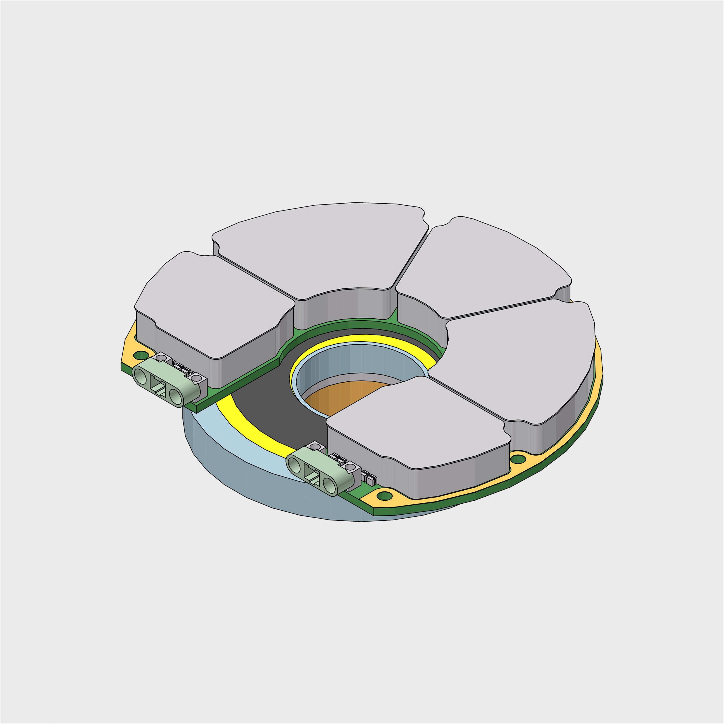
5) Diameter of the device was set at 100mm due to market considerations. This caused the CPU and PSU compartments to become densely populated.
6) The PCB layout was compartmentalised due to EMI and structural considerations (device to comply with MIL-STD-810H and MIL-STD-461G).
7) PCB and components to allow hand soldering during maintenance. We believe in a circular economy.
-
The Power Supply design for the MFEA Encoder complies with the following:
1) Flyback converter running at 500kHz, yielding a small design that could be fitted into one of the MFEA Encoders EMI compartments.
2) Galvanically isolated power supply as per DeviceNet standard.
3) Produces +3.3Vdc as per SmartFusion requirement. Also produces highly stable +5Vdc and -5Vdc to drive Colpitts Oscillators.
-
Partial Build 1 powered up for the first time. Blue LED indicates that Power Supply generates +3.3 Vdc. A resistor was added to emulate the load of the CPU that would be added in Partial Build 2.
-
Some design errors in the Power Supply were discovered during the evaluation and testing of Partial Build 1. This required the addition of some capacitors to minimize ripple and eliminate some pesky oscillations.
-
The worldwide chip shortage did not make it easy to acquire these, but we were helped by WinSource Electronics.
-
CPU compartment populated and operational. Colpitts Oscillator compartments populated, but not enabled.
-
Our initial attempt to program and debug the cSOC of Partial Build 2 proved problematic. This was caused by the severe PCB real-estate constraints of the CPU compartment, preventing the installation of a header connector. As a result, FlashPro4 signals had to be routed via PCB, Gecko Connectors, and Adapter Harness before reaching the ribbon cable of FlashPro4 as intended by Microchip for the FlashPro4 programmer. This arrangement created parasitic loads and cross-coupling between these signals that prevented the proper operation of the FlashPro4 programmer. The problem took many months to solve requiring extensive adaptation of the JTAG interface in collaboration with Microchip.
-
Some problems during debugging of Partial Build 2 caused failure of the cSOC. Replacing the cSOC without disturbing surrounding components on a very dense PCB proved to be a challenge. To do it we developed our own technique comprising an aluminium foil mask, pre-heating the PCB with infrared from below and hot air from above. Basically, the same technique will be used in future during maintenance operations.
-
One of the failure mechanisms discovered on Partial Build 2 was overshoot of the Power Supply during switch-on. This damaged the cSOC. To prevent this a Crowbar circuit was introduced, adding real estate to the Power Supply compartment. On subsequent models the modified Power Supply will be added in the form a separate double sided PCB referred to as the Piggy-Back. In this approach the Piggy-Back becomes a separate component which can be repackaged and marketed as a standalone device.
-
While developing the software of the Auto-Align Algorithm the code exceeded 64 kilobyte. This prevented debugging in RAM and forced us to debug in onboard FLASH memory. This caused timing problems in the JTAG connection between cSOC and the FlashPro4 programmer. To overcome this problem we had to resort to a dedicated display driven by I2C interface between cSOC and display. Although very cumbersome and slow, this enabled us to see what the software was doing and debug the algorithm.
In our attempts to solve the JTAG problem as mentioned above, the front-end circuit of the FlashPro4 was acquired from Microchip. This enabled us to design an adapter board for the FlashPro4 interface, solving timing and EMI (cross-talk) problems of the interface. Getting both green LED’s of the FlashPro4 to light was a major achievement.
-
Auto-Align algorithm running after successful programming of onboard FLASH memory using Adapter Board and Ferrite Ring to solve EMI (cross-talk) and noise problems of the JTAG interface. This called for various measures, including shunting noise right at the Header and filtering the VPUMP and VJTAG supplies. Routing the JTAG signals via the MFEA Encoder PCB causes additional capacitive loading of the TCK signal. This problem was solved by boosting the TCK driver in FlashPro4 with a dedicated push-pull stage on the Adapter Board which yielded sufficient rate of change of the TCK signal. If you would like to know more about our solution pop us a mail.
-
Milestone achieved! The waveform generated by cSOC as measured by the oscilloscope on the right corresponds with the waveform generated by the mathematical model running in Simulink on the left. Thank you Manisha and Leonardo from Microchip for helping us to get the SoftConsole compiler and JTAG interface to work!